
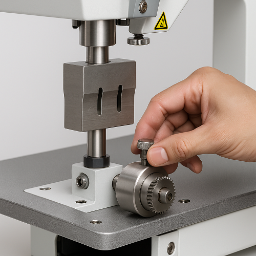
Technical guidance demonstrated directly on a VietSonic ultrasonic sewing machine

Proper ultrasonic horn alignment and welding roller removal and installation

The video directly demonstrates the process of aligning the ultrasonic horn, removing the roller, inspecting the mounting assembly, and returning the roller to its working position on the ultrasonic sewing machine. Each step shows how the machine is designed for convenient operation, pattern changes, and technical inspection.

Horn alignment
Control the contact position between the ultrasonic horn and the roller
Roller removal and installation
Convenient for cleaning, inspection, or pattern replacement
Test run after installation
Directly evaluate the weld seam on sample material
Content closely follows the actual video

Why should the horn and roller be aligned before production?

On an ultrasonic sewing machine, the material passes through the contact area between the ultrasonic horn and the welding roller. The horn transmits ultrasonic vibration, while the roller applies pressure and forms the weld pattern on the material surface.

These two components must be positioned correctly and make even contact. If the horn is misaligned, the roller is installed off-axis, or the contact pressure is unsuitable, weld quality will immediately be affected.

  • The weld seam may be uneven from one side to the other.
  • Some areas may not bond or may not be welded firmly enough.
  • The material may be over-compressed, torn, or burned.
  • The horn and roller may develop uneven wear.
  • The machine may vibrate or produce unusual noise.

Therefore, horn alignment and roller removal and installation are important technical procedures during operation, cleaning, or weld-pattern changes.

VietSonic ultrasonic sewing machine for horn alignment and welding roller removal and installation

Video: horn alignment and welding roller removal and installation

The video directly shows the machine areas involved, how to align the horn assembly, and how to remove the roller from the shaft before reinstalling it.

Watch the entire video before starting so you can correctly identify the adjustment points, the shaft-locking mechanism, and the roller installation direction.

Items to inspect before alignment

Before adjusting the screws or removing the roller, the operator should inspect the entire working assembly to avoid making adjustments based on the wrong cause.

01

Horn surface

Check whether the horn is cracked, bent, scratched, or unevenly worn.

02

Center position

Check whether the horn is positioned within the roller’s correct working area or shifted to one side.

03

Parallel alignment

Check whether the horn surface is parallel to the roller’s contact surface.

04

Locking mechanism

Check the retaining screws, roller shaft, and locking points for looseness before operation.

Ultrasonic horn alignment procedure

The steps below follow the machine demonstration shown in the video. The operator should work gradually and recheck the assembly after each adjustment.

Switch off the machine and place the working assembly in a safe state

Disconnect the electrical power and compressed-air supply if the machine uses pneumatics. Do not perform alignment while the horn or roller is still operating.

Move the horn to the center position

Observe the horn position relative to the roller and move it into the correct working area. Centering helps distribute pressure more evenly across the weld seam.

Inspect the horn surface

Inspect the horn for cracks, bending, wear, or damage. Do not continue pressing the horn against the roller if the horn surface shows any abnormal signs.

Lower the horn gradually

Set the machine to manual mode and use the adjustment wheel to lower the horn gradually into the working position. Do not lower it quickly or press it forcefully against the roller.

Adjust the parallel alignment

Observe the contact gap between the horn face and the roller. If one side makes contact first or the gap is uneven, use the fine-adjustment screws to correct the horn assembly angle.

Tighten the locking points after alignment

Once the horn face is correctly positioned and parallel to the roller, retighten the locking points. Recheck the assembly afterward to ensure that tightening has not shifted the horn.

Note: Do not press the horn too firmly against the roller. Excessive pressure can accelerate horn and roller wear and may cause the material to be cut too deeply, torn, or burned during the test run.
Aligning the ultrasonic horn position on a VietSonic ultrasonic sewing machine
The horn assembly must be positioned in the correct working area and aligned parallel to the roller surface.

Procedure for removing the welding roller from the machine

The roller makes direct contact with the material and determines the shape of the weld pattern. Correct removal protects the patterned surface, retaining shaft, and drive mechanism.

Remove the roller

  • Operate the lever or locking mechanism to lift the roller shaft out of the working position.
  • Identify the screw or component securing the roller to the shaft.
  • Use the appropriate tool to loosen and remove the retaining screw.
  • Hold the roller securely while pulling it off the shaft.
  • Remove it carefully to prevent the roller from falling or striking the machine body.

Clean and inspect

  • Use a soft cloth to remove dust, material fibers, and oil from the roller.
  • Check the patterned surface for uneven wear.
  • Inspect the shaft bore and the roller’s mounting surfaces.
  • Do not use hard objects to scrape the patterned surface directly.
  • Replace the roller if cracks or visible deformation are found.
Removing the welding roller from the shaft of a VietSonic ultrasonic sewing machine
The roller is removed from the shaft for cleaning, inspection, or weld-pattern replacement.

Reinstall the roller in its working position

After cleaning or replacing the roller, install it correctly on the retaining shaft and check its stability before test-running the machine.

Inspect the shaft and mounting position

Clean the retaining shaft, inspect the locking screw, and remove any dust or material remaining at the roller mounting position.

Fit the roller onto the correct shaft

Orient the roller correctly and slide it gradually onto the retaining shaft. Do not force or hammer it into place, as this may misalign the shaft or damage the mating surfaces.

Tighten the roller retaining screw

Tighten the screw so the roller cannot shift during operation. Make sure the roller is not tilted or displaced from the horn’s contact area.

Return the roller to the working position

Operate the lever or locking mechanism to return the roller to its operating position. Check the contact gap with the horn before switching on the machine and feeding material.

Installing the roller in the working position on a VietSonic ultrasonic sewing machine
After installation, the roller must be correctly aligned on the shaft and within the ultrasonic horn’s contact area.

Test run and inspection after installation

Do not move directly into mass production immediately after alignment. Use sample material to reassess the weld seam and the contact between the horn and roller.

Weld seam uniformity

Check whether the weld seam is continuous, clearly formed, and uniform across the full width.

Bond strength

Check whether the two material layers are securely welded or whether any areas remain unbonded.

Material condition

Check whether the material is torn, deformed, burned, or cut too deeply.

Roller operation

Check that the roller rotates steadily, remains properly aligned, and does not create abnormal vibration.

When the weld seam does not meet requirements

Stop the machine and recheck the horn height, parallel alignment, and contact pressure. Do not simply increase ultrasonic power to compensate for a misaligned mechanical assembly, because the underlying positioning problem remains unresolved.

Machine-building capability is reflected in operation and maintenance

The video does more than demonstrate a technical procedure. The machine structure and accessibility of each component allow businesses to evaluate how convenient the machine is to operate in actual production.

01

Adjustable mechanism

The horn assembly includes adjustment points and locking positions, allowing technicians to control its height, position, and parallel alignment when required.

02

Removable roller

The roller shaft and locking mechanism allow the roller to be removed for cleaning, inspection, or replacement according to the product’s weld pattern.

03

Direct on-machine guidance

The VietSonic team understands each mechanical assembly, adjustment point, and operating procedure, enabling direct operator guidance after machine delivery.

Machine manufacturing capability involves more than assembling equipment. The manufacturer must understand the relationship between the horn, roller, pressure, and material so the machine can be aligned, maintained, and kept operating reliably under actual production conditions.

VietSonic provides direct consultation, design, and manufacturing of ultrasonic sewing machines for specific processing requirements. Businesses can supply material samples, weld-pattern requirements, and target output so the technical team can determine a suitable machine configuration.

Need an ultrasonic sewing machine suited to your material?

Contact VietSonic to discuss your material, thickness, weld type, roller pattern, and production requirements. Our technical team will recommend a machine configuration based on the actual product rather than general specifications alone.